top of page

Complete Guide to IOL Power Calculation - Advanced Masterclass

Updated: Mar 27


The topics discussed in Masterclass are at an advanced level!

If you have not covered the basics, you are requested to first go through the Biometry section in this website, before you take the course.


The Masterclass in biometry is constantly updated.


Section 1

Understanding Modern IOL power calculation formula architecture:

1.1 Why different IOL power calculation formula behave differently


What do we mean by vergence?    Fig 1
What do we mean by vergence? Fig 1

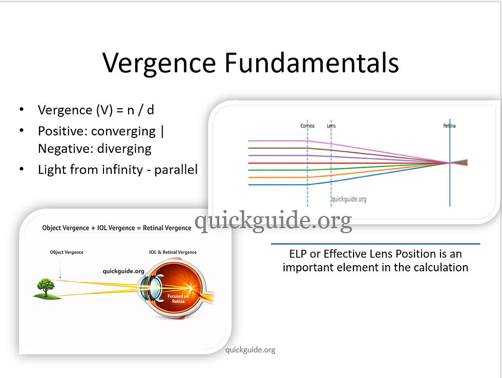
Vergence describes how “converging” or “diverging” a bundle of light rays is at a given plane in the eye. Parallel rays of light has zero vergence. As light rays pass through the cornea, the optical power of cornea makes the light rays converge. Vergence describes the converging power of cornea and how far the rays of light will travel further to reach the lens. Thus vergence studies the power of the cornea and the lens to converge the rays of light and the distance the rays of light travel, after passing through bother cornea and lens to reach the retina.


Vergence formula, v = n/d where n is the refractive index of medium and d is the distance the rays of light travel.


Thus all modern IOL formulas are fundamentally vergence based formula. First, they study the vergence of light rays (L) at the IOL plane, the emergent vergence of light rays (L') after they emerge passing through the IOL (which will have a certain power F).


The formula is therefore,

Fig 2a        Thus vergence of light rays passing after crossing the IOL is dependent of the refractive index of vitreous, and the length of the vitreous chamber through which the rays of light will travel to reach the retina.
Fig 2a Thus vergence of light rays passing after crossing the IOL is dependent of the refractive index of vitreous, and the length of the vitreous chamber through which the rays of light will travel to reach the retina.

In the equation above, vergence of light rays after passing through the IOL will have to take into account the refractive index of vitreous (numerator). The denominator, AL-ELP signifies the posterior segment length up to the retina (ELP is the distance between the cornea and the refracting plane of the IOL)


Similarly, the vergence of incoming rays of light that pass through the cornea and reach the IOL has to be also taken into account.


Fig 2b    Vergence of light rays after passing through the cornea where K is the corneal power, n is the RI of aqueous, ELP is the estimated lens position
Fig 2b Vergence of light rays after passing through the cornea where K is the corneal power, n is the RI of aqueous, ELP is the estimated lens position

By adding the vergence of equation in Fig 2a and 2b, we can arrive at the power of IOL. Remember, the above explanation is applicable to vergence based on thin optics lens provided by the mathematician, Gauss.


Fig 3      Difference between thin and thick lens optics        quickguide.org
Fig 3 Difference between thin and thick lens optics quickguide.org

Next we will see IOL calculation formula according to thin and thick lens mathematical formulas.


1.2

How do thin and thick lens IOL calculation vergence-based formulas differ?


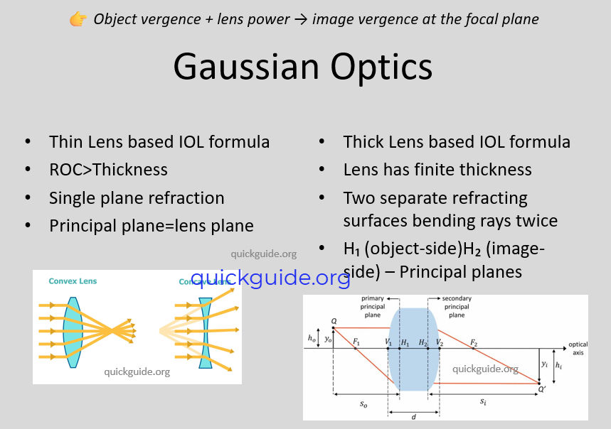
Power of any lens, be it glass power, or a lens used in microscope or telescope can be calculated mathematically by Gauss think and/or thick lens formula. In a thin lens formula, provided by Gauss, the lens is considered so thin that the thickness of the lens is not considered. The entire refraction is considered to happen in only one plane. IOL calculation formulas of second and third generation, like the SRK T, Hoffer Q, the Holladay I, etc. are based on thin lens optical formula of Gauss. ELP or effective lens position is the distance from the cornea to the refraction plane of the IOL.


In this context, it is important to remember that the ELP is not a physical distance from the cornea to the IOL refraction plane. It is a virtual value that is back-calculated from post operative refraction of pseudophakic patients, and built in the formula. It is a virtual distance, and not a physical distance from the cornea to the IOL refraction plane.


Fig 4        The thick optics lens power calculation. Note this vergence based formula takes into consideration the central thickness (t) which is reflected in the equation.           quickguide.org
Fig 4 The thick optics lens power calculation. Note this vergence based formula takes into consideration the central thickness (t) which is reflected in the equation. quickguide.org


On the other hand in thick lens formula, the lens thickness is taken into account. Thus in

thick lens formula there are two planes of refraction. These are the first and second

principal planes. For a biconvex IOL, the two principal planes sit inside the IOL. The focal

length of the IOL is the distance from the second principal plane to the point where all

rays of light converge.

Fig 5        The first and second principal planes of a lens. The focal length is the distance from the second principal plane to the red dot where the rays of light are converging.    quickguide.org
Fig 5 The first and second principal planes of a lens. The focal length is the distance from the second principal plane to the red dot where the rays of light are converging. quickguide.org


1.3

Which IOL formulas utilize the vergence formula for thin and thick optics?

The below (Fig 6) describes IOL power calculation formula that are based on vergence based thin optics or thick optics formula.

Fig 6       The red box indicate IOL calculation formulas that are based on thin optics mathematics, while the blue boxes indicate IOL calculation formulas that are based on thick optics mathematics.      quickguide.org
Fig 6 The red box indicate IOL calculation formulas that are based on thin optics mathematics, while the blue boxes indicate IOL calculation formulas that are based on thick optics mathematics. quickguide.org


The older two variable formula like the SRK T, Hoffer Q and Holladay I are based on thin optics vergence formula. These formulas do not consider the IOL as a thick optics lens. They assume that the entire refraction is happening in one single plane in the IOL.


1.4

What are the advantages of IOL calculation formula based on thick optics vergence formula?


The principal planes of refraction in an IOL is not a fixed position. It moves with the change in the IOL power. The rate of change of the position of the principal planes of refraction is more as you move from an average IOL power ( say 21.0 diopter) to a high power IOL ( say 30.0 diopter). The first principal plane shifts anterior, that is towards the anterior curvature of the IOL, while the second principal plane shifts towards the posterior surface of the IOL. Since the second principal plane shifts posterior as the curvature of IOL becomes more steeper (for a high power IOL), there is a chance of myopic surprise, when A constant of the IOL is not optimized for the high power IOL, that is hyperopes. Again, as IOL power increase, if the anterior curvature of the optic increase more sharply than the posterior optic curvature, then effective lens position moves more anteriorly leading to a myopic shift(3).


Add to this, different IOL manufacturing companies, have IOLs that do not change their anterior and posterior radius of curvature linearly from a low power IOL to a high power IOL. Therefore, using the same constant for high power IOLs may lead to refractive surprise. Shape factor is a term given to understand how an IOL shape changes as a function of anterior to posterior radius changes from a low to a high power IOL. Many IOL models are not biconvex symmetrical but have a nonzero shape factor S = (R1 + R2)/(R1 − R2), with R1 and R2 being anterior and posterior lens radii, respectively. This shape factor often changes between power levels which may cause refractive surprise when used with a standard constant (say A constant for the IOL).


Fig 7        The change in the principal plane location of two  IOLs with different refractive index as a function of the IOL power. Conceptual only       quickguide.org
Fig 7 The change in the principal plane location of two IOLs with different refractive index as a function of the IOL power. Conceptual only quickguide.org

The thick lens IOL calculation formula, like the Barrett Universal II formula, considers the changes in the principal planes of refraction as one moves from a low power IOL to an high power IOL. Barrett Universal formula is an unpublished formula. However, this formula has studied a standard AcrySof IOL, to understand how the principal planes of refraction shift.


1.5

Refractive Index(RI) of an IOL, and the change in principal planes of refraction based on IOL power. Which of the two IOLs will be more forgiving in short eyes?


Both IOLs with high and low refractive index(RI), will have a change in the location of second principal plane of refraction with change in IOL power. This can lead to unexpected refractive surprise. But the change in the second principal plane of refraction between an IOL with high RI is less than with an IOL with lower RI. Therefore an IOL with a RI of 1.55 will be more forgiving than an IOL with a RI of 1.47.


The following is proposed as an adjustment to IOL power calculated for high power IOLs (3).


Adjustment to calculated IOL power for high power IOLs of three different IOLs   Source:  Journal of Cataract & Refractive Surgery 51(11):p 1039, November 2025. | DOI: 10.1097/j.jcrs.0000000000001772    quickguide.org
Adjustment to calculated IOL power for high power IOLs of three different IOLs Source: Journal of Cataract & Refractive Surgery 51(11):p 1039, November 2025. | DOI: 10.1097/j.jcrs.0000000000001772 quickguide.org


1.6

What is the difference between modern thick lens IOL calculation formula like the Barrett and the EVO or Olsen formula?


Earlier I have explained the difference between the older two variable formula and the Barrett formula, that is formulas that are based on thin lens optics, and formula like Barrett or Olsen which is based on thick lens optics.


Now we will cover what is the difference between Barrett, Olsen and EVO formulas which are all based on thick lens optics. A detailed description is given in the following article : A Brief explanation of modern IOL power calculation formulas https://www.quickguide.org/post/a-brief-explanation-of-modern-iol-power-calculation-formulas


Barrett Universal II

Olsen Formula

EVO

Kane

Paraxial vergence based thick lens formula

Ray tracing thick lens formula

Paraxial vergence based thick lens formula

Thin lens formula with regression analysis and Artificial intelligence

Paraxial based- does not take into account over refraction beyond paraxial zone.

Takes into account positive spherical aberration through ray tracing beyond the paraxial region

Does not account for spherical aberration that takes place when rays pass through periphery of cornea

Does not account for spherical aberration.

Based on Gaussian thick lens formula

Based on Snell's law of refraction at each corneal interface

Based on Gaussian thick lens formula

Based on Gaussian thin lens formula.

No sum of segments or CMAL modification of axial length

No sum of segments or CMAL modification of axial length

Uses sum of segments approach through CMAL modification of axial length by turning axial length based on group refractive index into CMAL modified axial length

No sum of segments approach.

Physical details of particular IOLs are not required

Because of application of ray tracing physical details of IOLs like lens thickness and refractive index along with radius of curvature of anterior and posterior surface of IOL of a 22 diopter standard IOL required

Physical details of particular IOLs are not required

Physical details of particular IOLs are not required


Section 2

Role of Effective Lens Position (ELP) vs Predicted ACD in IOL Power Calculation

What Is Effective Lens Position (ELP)? How is it different from predicted ACD?


ELP is the theoretical axial location of the IOL’s principal plane used inside the vergence formula to predict postoperative refraction.


Key characteristics:


It is not the physical location of the IOL optic. It is a mathematical construct inside the formula.

It determines the effective optical power delivered at the retina. Thus it is a virtual number and not a physical or real number. It is arrived by IOL calculation formulas by understanding refractive outcomes and back calculating the ELP value through regression formula.


On the other hand, predicted ACD is the estimated postoperative distance from the corneal reference surface (usually epithelium) to the anterior surface of the IOL. Thus it is a physical distance.


My own calculator here helps you to understand the predicted ACD based on pre operative ACD and lens thickness. Post operatively you can do a pseudophakic biometry and see how far is the IOL sitting from the cornea and match with the predicted ACD. This will give you an idea if any refractive surprise is the result of post operative physical position of the IOL.


Fig 8     Predicted IOL position based on preoperative ACD and/or lens thickness (LT)        quickguide.org
Fig 8 Predicted IOL position based on preoperative ACD and/or lens thickness (LT) quickguide.org

Click to access the predicted ACD calculator: https://tinyurl.com/ELP-calculator


2.2

What is the method of ELP prediction by different IOL calculation formulas?


Different IOL calculation formulas employ different strategies to predict ELP. The thin optics based Holladay I and SRK T formulas predict ELP based on patient axial length and corneal readings. Haigis formula however does not use corneal power as a method to predict ELP. Instead the Haigis formula uses the axial length and pre operative ACD to predict ELP, a point to be noted which will be useful in our discussions for post lasik IOL calculation formula.


In predicting the postoperative ACD, SRK T adopts corneal height formula, which is a combination of corneal curvature, corneal width (White to White) and an off set factor to account for lens position from iris plane after implantation. Since the formula was developed in the early 1990s, there was very little means of knowing corneal width in an average practice, therefore, regression based formulas were applied to understand corneal width and then apply a theoretical formula to derive corneal height.


The height (H) of the corneal dome is computed from the corneal width (width) and the corneal curvature (r):


ACD (postoperative) = corneal thickness+ H + offset factor (refer diagram above)         quickguide.org
ACD (postoperative) = corneal thickness+ H + offset factor (refer diagram above) quickguide.org

where H is corneal height derived from corneal curvature and corneal width and the offset factor is to account for the distance from iris to IOL plane for an average eye ( offset = ACDconst - 3.336). Like SRK T, the Hoffer Q and Holladay 1, use the corneal curvature to predict the ELP.


The Haigis formula does not predict the ELP based on corneal height formula. Instead it depends on three constants (a0,a1,a2) to determine the final position of the IOL.


a0 — Base IOL Position


Represents the baseline predicted IOL position.

It mainly reflects:

  • IOL design

  • Surgical technique

  • A-constant–like behavior

Think of it as the starting point of the predicted ELP.

a1 — Influence of Pre-operative ACD


The diagram usually shows a deeper anterior chamber moving the predicted IOL backward.

Meaning:

  • Large pre-op ACD → IOL predicted more posterior

  • Small ACD → IOL predicted more anterior

This reflects the idea that bigger anterior segments tend to place the IOL deeper.

a2 — Influence of Axial Length


The picture often shows longer eyes shifting the IOL slightly posteriorly.

Long eyes generally have:

  • Larger capsular bags

  • Deeper IOL position

Thus axial length modifies the predicted ELP.


Difference between SRK T/Holladay 1 and the Haigis    quickguide.org
Difference between SRK T/Holladay 1 and the Haigis quickguide.org

Amongst the thick lens formulas, the Olsen uses the C constant method that in turn predicts ELP based on lens thickness and pre operative ACD. Barrett uses the Lens Factor to predict the ELP, which in turn is based on the A constant of IOL, the corneal power, axial length, the white to white and the lens thickness.


ELP prediction - how different thin and thick lens formulas predict

Holladay 1

SRK T

Olsen

Kane

Barrett

Haigis

Surgeon Factor (SF) - distance from Iris plane to IOL refracting plane

A constant - virtual distance from cornea to refracting plane

C Constant - a constant that predicts the position according the ACD and LT

A constant

Lens Factor (LF) - distance from Iris plane to second principal plane of refraction.

a0, a1, a2 constants

a0 - predicts base IOL position

a1- depends on pre operative acd

a2- depends on AL.

Inputs considered

Corneal Height formula - combination of corneal curvature, WTW, and an off set factor to account for IOL position distance from Iris plane

Corneal Height formula along with AL and K reading

ACD and Lens thickness

AL, K reading, ACD, LT (optional)

AL, K reading, ACD, LT (optional)

Measured ACD and AL


Key point to remember - Predicted ACD is a physical distance from the corneal epithelium to the anterior surface of the IOL, while ELP is a virtual distance built in the IOL formula from the cornea to the principal plane of refraction of the IOL. In a thick lens formula like Barrett Universal II, the ELP corresponds to a virtual distance from the corneal second principal plane to the second principal plane of the IOL.


2.3

What is the impact of post ACD error on refraction of patient?


Olsen states that ±0.7 mm axial displacement of the IOL is the equivalent to a ±1 D shift in IOL power in a normal sized eye. The effect is, however, very dependent on the axial length of the eye. Generally, for an average axial length, a .1 mm of IOL displacement may result in a .19 diopter effect on the refractive outcome. The refractive error is more pronounced in short eyes and less pronounced in high axial length patients.


Why the Relationship Is Not Fixed?

The refractive effect of an ELP (post-ACD) shift depends on:

  • IOL power - Higher IOL power will create a larger refractive shift with a .1 mm post-ACD error

  • Axial length- Shorter axial length (axial hyperopia) will have a larger refractive shift for every .1 mm of error

  • Corneal power- Steeper cornea is generally more forgiving to ELP (post-ACD) error, while a flatter cornea is more sensitive to the same amount of IOL position shift.

  • Distance of the IOL from the cornea


The refractive effect of an IOL shift depends on the relative contribution of the IOL to the total optical power of the eye.

Total power of the eye:

Power of eye=Power of cornea+ Power of IOLF​


When the cornea is steep:

  • Corneal power is higher

  • The relative contribution of the IOL becomes smaller

  • Therefore movement of the IOL changes the total system power less

When the cornea is flat:

  • Corneal power is lower

  • The IOL contributes more to the total optical system

  • Therefore ELP errors produce larger refractive change


A conceptual relationship between the power of the cornea and the effect on refractive error of different IOL powers with a .1 mm shift in postACD (ELP)       quickguide.org
A conceptual relationship between the power of the cornea and the effect on refractive error of different IOL powers with a .1 mm shift in postACD (ELP) quickguide.org


Because of these factors, the relationship is not linear and not constant across eyes.


Section 3

Total Keratometry & Posterior Cornea Concepts

3.1

What is the power of cornea per the Gullstrand model eye?


The Gullstrand model eye has a radius of curvature of 7.7 mm and 6.8 mm for the anterior and posterior cornea, respectively. Taking this into consideration the power of the anterior and posterior cornea are 48.83 D and - 5.88 D (remember that the cornea has a meniscus shape and therefore the posterior cornea has a negative power). Thus the Net power of Cornea is 43.03 when taking into account the refractive index of cornea as 1.376 and that of aqueous as 1.336.


3.2

How does traditional Keratometry machines measuring only anterior cornea arrive at the value of Gullstrand net power of cornea?


However we know that traditional keratometry machines do not measure the power of the posterior cornea. By measuring the anterior curvature of cornea, and by taking into account the Gullstrand standard anterior posterior ratio of 82%, they arrive at the net power of cornea by employing a fictitious keratometry index of 1.3375 (some machines may have different keratometry index). Thus after measuring the anterior curvature of cornea, they use the thin lens formula D=n-1/r, to arrive at a net power of cornea that is closer to the Gullstrand eye. In this formula, n is the keratometry index of 1.3375, '1' is the RI of air, and r is the radius of curvature measured by the keratometry machine.


3.3

How does IOL Master TK differ from net power or cornea as measured by TCP of Pentacam?


The IOL Master TK measures the posterior cornea, but provides corneal power in a way that match traditional keratometry machines that employ a keratometry index of 1.3375. The values of TK are not that of net power of cornea. Here I should mention that though traditional keratometry machines arrive at net power of cornea by applying the keratometry index of 1.3375, yet the values are still higher than Gullstrand net power of cornea. For example, taking a keratometry index of 1.3375 and a measured radius of curvature of anterior cornea as 7.7 mm, the traditional keratometry machines arrive at a value of 43.8 diopters, which is still higher that Gullstrand net power of cornea of 43 diopters ( considering the radius of curvature of anterior and posterior cornea as 7.7 and 6.8 mm). Thus all IOL calculation formula, reduce the power of cornea as measured and input, by up to 1 diopter to match the Gullstrand net power of cornea.


If IOL Master 700 provided the net power of cornea per the thick lens formula, then a- constant needs to be changed. Therefore, TK is derived from a measured anterior and posterior cornea values, but adjusted to match values with a keratometry index of 1.3375. What it means for clinicians is that, there is no need for change in a-constant values when a surgeon moves from IOL Master 500 to IOL Master 700. This is further explained in the below video:


Explanation of IOL Master 700 Total Keratometry quickguide.org

3.4

If IOL Master TK is adjusted to match traditional Keratometry values, where does it have an advantage?


Great question!


In average eyes with a normal anterior/posterior ratio, IOL Master TK will have very little clinically relevant difference with traditional keratometry based on anterior cornea measurements(2). However, the difference will be more in post Lasik patients, or patients with abnormal cornea, like keratoconus, where the normal A/P ratio is disturbed.


Fig 9     In normal eyes there is no major difference between corneal reading based on anterior measurement only and total keratometry           quickguide.org
Fig 9 In normal eyes there is no major difference between corneal reading based on anterior measurement only and total keratometry quickguide.org

Note, in fig 9, there is only a difference of .08 diopters between corneal power based on TK (44.81 D) and anterior K readings only (44.73 D). However, in post Lasik patients, the TK is useful as Lasik changes the A/P ratio (Fig 10 highlighted in yellow).


Fig 10
Fig 10


3.5

IOL Master 700 TK vs TCRP from Pentacam

There is a fundamental difference between IOL Master 700 TK values, and Pentacam TCRP, though both takes into consideration posterior corneal values. IOL Master 700 TK is the next version of IOL Master 500. In IOL Master 500, the central 2.5 mm ring was measured. With an average prolate cornea, this value will be steeper than what manual keratometry would measure in the 3.2 mm of the cornea. Therefore, to adjust to the steeper values of the keratometry reading with the IOL Master, the recommendation is to take a higher A-constant, generally .3 higher than manual keratometry based A constant.


The confusion with IOL Master 700 corneal reading values - 

The IOL Master 700 measures in three rings - 1.5, 2.5 and 3.5 mm of the cornea. If corneal readings of the three rings are to be taken into account for the IOL power calculation, adjustment to the a constant has to be done, for a surgeon graduating from IOL Master 500 to IOL Master 700. However, there is no guidance from the company with regard to adjustment of constant values, to the best of my knowledge.


One situation could be that, the IOL Master 700 could still be considering the central 2.5 mm of the cornea for the IOL power calculation. In that case, a surgeon moving from IOL Master 500 to IOL Master 700 will not need to further adjust a-constant values for a particular IOL. More explanation from the company would clear the air here.


The Pentacam TCRP values are true Net power of the cornea. It applies Gaussian thick lens formula (earlier described) and Snell's law of refraction. In doing so, it applies the refractive index of cornea, air and aqueous and takes into consideration the relationship between the incident rays of light and the refracted rays of light per the Snell's law of refraction. To know more about the various Pentacam maps including TCRP, you may refer to the page https://www.quickguide.org/post/the-keratometry-or-corneal-reading-calculation-dilemma-for-post-refractive-lasik-patients


 Fig 11          True Corneal Refractive Power of central 3.0 mm of cornea       quickguide.org                                                                Source: https://www.oculus.de/en/products/pentacam-family-software/
Fig 11 True Corneal Refractive Power of central 3.0 mm of cornea quickguide.org Source: https://www.oculus.de/en/products/pentacam-family-software/

3.6

Which zone of the TCRP map in the Pentacam should be considered for IOL power calculation?


Why did the manual Keratometry measure an area of 3.2 mm of the cornea? This was done taking into account 3.0 mm as an average value of photopic and mesopic pupil diameters. Considering a measurement zone of 3.2 mm would mean a good balance between the photopic and mesopic pupil diameters.


In manual Keratometry which measures around 3.2 mm of corneal ring, the area within a 3.2 mm circle is 32.17 mm² . The area of a 4.5 mm circle (mesopic pupil size) is 63.62 mm². Thus manual keratometry measured an area of 3.2 mm that would be the area of the cornea that is 50% inside and 50% outside the circle (remember keratometry measurements are not done in zone, but an area over the circle of measurement), explains Dr Jack Holladay, in several of his lectures.


With optical biometry, measurements are done in much smaller area, like the IOL Master measures 2.5 mm or the Lenstar over two rings of 1.63 mm and 2.3 mm. Thus with optical biometry adoption, adjustment to A constant is required, that is around .3 higher than a manual keratometry based IOL power a constant.

This brings to our discussion back to TCRP map from Pentacam, or the TCP map from Galilei. Which zone should be considered for measurement. Remember here, the TCRP readings reflect the power of the cornea in the zone of measurement ( say 3.0 mm or 4.0 mm). It is not the same as the IOL Master or Lenstar measurements that measure a ring on the cornea. I would strongly recommend to consider the values of TCRP 3.0 for virgin cornea, and 4.0 mm for the post lasik patients. Applying TCRP zones lower than these areas may have the following effect for the two different corneas as follows:


For virgin prolate cornea, a smaller TCRP zone consideration for IOL power calculation (say 1.0 mm) may result in two steep a power of cornea, resulting in lower IOL power. This will lead to hyperopic surprise. In a study by Jin and co-authors (1) The IOL Master 700 had the highest mean total keratometry (TKm; 44.23 ± 1.59 diopters [D]), followed by Pentacam AXL (43.94 ± 1.68 D).

For post myopic Lasik patients, too small TCRP zone consideration may lead to flatter values of cornea, leading to higher IOL power that may lead to myopic refractive surprise.
TCRP vs IOL Master TK: IOL Master TK is measured in a smaller area, which could lead to flatter values of cornea for post lasik patients, which unless corrected by the IOL calculation formula, may lead to refractive surprise in comparison with TCRP values.


Section 4:

Validating the measurement from Optical Biometry


4.1

How reliable are the measurements for the IOL power calculation?


Here is a check list that you may try to validate the data from an optical biometry device. Remember to always do a two eye biometry (operating as well as the non operating eye) to help validate the data and corelate measurements between the two eyes.


Fig 12    Quick validation guidelines for IOL Master         quickguide.org
Fig 12 Quick validation guidelines for IOL Master quickguide.org

Validation guidelines from IOL Master version 5.4


The following plausibility tests will be made with the keratometer

reading:


  • R > 8.4 mm 􀀾 Indicates possibility of a very flat corneal curvature

  • R < 7.2 mm 􀀾 Indicates possibility of a very steep corneal curvature

  • R1 - R2 > 0.5 mm 􀀾 Indicates high astigmatism

When both eyes have been measured, the difference in the keratometer

readings between the right and left eye will be checked. If this exceeds

0.2 mm or 1 D, you will be prompted to check the readings once again.


When the SNR values in biometry, using IOLMaster, are <10, careful attention should be

given to determining IOL power(4).


Fig 13     IOL Master 700 helps understand if the patient's eye was fixated on the foveal pit during the meausrement     quickguide.org
Fig 13 IOL Master 700 helps understand if the patient's eye was fixated on the foveal pit during the meausrement quickguide.org

Fig 14    Quick validation guideline for Lenstar           quickguide.org
Fig 14 Quick validation guideline for Lenstar quickguide.org

Fig 15    Tomey OA-2000 validation guidelines    quickguide.org
Fig 15 Tomey OA-2000 validation guidelines quickguide.org

A good reading with Tomey OS-2000 for AL should have the following features:

Distinct peaks depicting B ellipsoid zone, C Retina and D sclera. Additionally, ILM membrane (A) may be visible

Additionally, the SNR value should be higher than 3.


A low astigmatism ( <1 diopter) with high standard deviation may often be caused due to dry eyes. You could also suspect dry eyes if there is a high standard deviation of axis (>3.5 degrees) with low astigmatism.


Fig 16     K readings more than 47.2 diopters or less than 41 diopters need to be rechecked and validated. To high or too low corneal powers may indicate an underlying irregularity of cornea. In such cases a topography is useful.               quickguide.org
Fig 16 K readings more than 47.2 diopters or less than 41 diopters need to be rechecked and validated. To high or too low corneal powers may indicate an underlying irregularity of cornea. In such cases a topography is useful. quickguide.org


manual keratometry measured an area of 3.2 mm that would be the area of the cornea that is 50% inside and 50% outside the circle (remember keratometry measurements are not done in zone, but an area over the circle of measurement), explains Dr Jack Holladay, in several of his lectures.


4.2

Investigating a refractive surprise

Three cardinal questions to ask!


It is natural to come across refractive surprise after IOL implantation despite a good biometry. The three cardinal questions to ask to arrive at a logical conclusion are:


Fig 13      The three questions that are relevant to investigate any refractive surprise following IOL implantation         quickguide.org
Fig 13 The three questions that are relevant to investigate any refractive surprise following IOL implantation quickguide.org

Fig 17          Preoperative(left image) and postoperative (right image) of the left eye of a patient.        quickguide.org
Fig 17 Preoperative(left image) and postoperative (right image) of the left eye of a patient. quickguide.org

In Fig 17, preoperative and post operative left eye details are visible. Below in Fig 18, a projected value of post operative ACD from the measured pre operative LT and ACD shows a large discrepancy between the projected ACD and the actual lens position in the left eye.


Fig 18            My calculator helps you understand the predicted actual lens position of the IOL based on the preoperative ACD and LT, that would help you to rule out a large mismatch in effective lens position after IOL implantation          quickguide.org
Fig 18 My calculator helps you understand the predicted actual lens position of the IOL based on the preoperative ACD and LT, that would help you to rule out a large mismatch in effective lens position after IOL implantation quickguide.org

Calculator for predicting actual lens position based on LT and ACD can be accessed with the following link: https://tinyurl.com/ELP-calculator


With refractive surprise a post operative pseudophakic biometry report is therefore essential. A common reason of refractive surprise is the change in corneal power post cataract surgery and IOL implantation. An IOL power calculated with a pre operative cornea spherical power of 42 diopter, will lead to a myopic surprise, if the post operative corneal spherical power increases even by .5 diopters. Similarly a large difference between pre operative and post operative axial length could indicate discrepancies in biometry.


4.3

Second Eye IOL Power Calculation


When there is a refractive surprise in the first eye.


Imagine you encounter a refractive surprise of +1 diopter in the first eye of the patient. How will you plan for the second eye? Many surgeons target a full correction for the second eye. However, recent peer reviewed papers are showing, that rather than a full correction, that is targeting myopia of equal amount of the refractive surprise, the following approach may be more appropriate.


  • First eye targeted spherical equivalent -.50 diopter

  • Subjective refractive outcome- +1 diopter

  • Total or absolute refractive error equals to 1.50 diopter ( difference between target refraction and actual refraction).

  • Determine IOL power with same target refraction as of first eye (say 21 diopter for -.50 in second eye)

  • Add 1/2 of absolute refractive error from first eye to 21 diopters, that is 21 diopters + .75 diopter. This equals to 21.75 diopter, rounded off to 22 diopters.


Here is a video explanation to the approach and a calculator that could be used for determining the second eye IOL power:


Video explaining the approach to second eye IOL power calculation quickguide.org


This is an ongoing article and keep an eye on this blog for frequent updates


-----------------------------------------------------------------------------------------------------------------------------------

(1) Aixia Jin; Xiaotong Han; Jiaqing Zhang; Xiaozhang Qiu; Yifan Zhang; Bo Qu; Xuhua Tan; Lixia Luo, Agreement of Total Keratometry and Posterior Keratometry Among IOLMaster 700, CASIA2, and Pentacam, Translational Vision Science & Technology March 2023, Vol.12, 13. doi:https://doi.org/10.1167/tvst.12.3.13


(2) Jascha A. Wendelstein, Peter C. Hoffmann5 ∙ Kenneth J. Hoffer6,7 ∙ … ∙ Theo G. Seiler1,16,17 ∙ Martin Zinkernagel16 ∙ Giacomo Savini, Differences Between Keratometry and Total Keratometry Measurements in a Large Dataset Obtained With a Modern Swept Source Optical Coherence Tomography Biometer, Volume 260p102-114April 2024


(3) David L. Cooke, MD, Michael S. Seward, MD, Timothy L. Cooke, BA, Improving refractive predictability with

high-powered intraocular lenses: refractive implications of various optic designs, J Cataract Refract Surg 2025; 51:600–606


(4) So Jung RyuID and others The influence of low signal-to-noise ratio of axial length measurement on prediction of target refraction, achieved using IOLMaster, PLoS ONE 14(6): e0217584. https:// doi.org/10.1371/journal.pone.0217584

Services

Online consultation

online consultation.jpg

If you are interested to learn more on any of the content in this website, you are free to subscribe and drop me a message for an online consultation against a coffee.

Educational Purpose Only
The content provided on quickguide.org is intended solely for educational and informational purposes and is designed for eye‑care professionals, trainees, and industry professionals with relevant clinical or technical background.
 No Medical Advice
The information on this website does not constitute medical advice, diagnosis, treatment recommendations, or clinical protocols. It should not be used as a substitute for professional training, clinical judgment, manufacturer instructions for use (IFU), or institutional guidelines.
Clinical Responsibility
All clinical decisions, including but not limited to biometry measurements, IOL power calculations, formula selection, and surgical planning, remain the sole responsibility of the treating clinician. Users are expected to independently verify data and apply appropriate professional judgment.

bottom of page